Linear Entities Processing
Suppose you have a workflow with OCR, a Segment Detection pipeline, a Corner Detection
pipeline, Spline versus Segment classification pipeline for example.
Otary allows you to instantiate linear entities representing the objects you are
manipulating such as Points, Segments, Splines and much more.
You can then display them on the image to visualize the objects you are
manipulating in your workflow.
Basic Example
| from otary import (
Image,
Segment,
Polygon,
Rectangle,
VectorizedLinearSpline,
OcrMultiOutput,
SegmentsRender,
LinearSplinesRender,
OcrSingleOutputRender,
PolygonsRender,
PointsRender,
)
from otary.geometry.discrete.linear.directed.entity import DirectedLinearEntity
points = ... # instantiate your contour list of points
dle: list[DirectedLinearEntity] = ...
ocrmo: OcrMultiOutput = ...
colors = [
interpolate_color(i / len(dle)) for i in range(len(dle))
]
for linear_entity, color in zip(dle, colors):
if isinstance(linear_entity, VectorizedLinearSpline):
im.draw_splines(
splines=[linear_entity],
render=LinearSplinesRender(
thickness=5,
default_color=color,
as_vectors=True,
pct_ix_head=0.25,
),
)
elif isinstance(linear_entity, Segment):
im.draw_segments(
segments=[linear_entity],
render=SegmentsRender(
thickness=5, default_color=color, as_vectors=True
),
)
else:
raise RuntimeError(f"Unknown type {type(linear_entity)}")
im.draw_ocr_outputs(
ocr_outputs=ocrmo.ocrsos,
render=OcrSingleOutputRender(thickness=2, colors=colors),
)
im.draw_points(
points=points,
render=PointsRender(thickness=10, default_color=(0, 0, 0)),
)
|
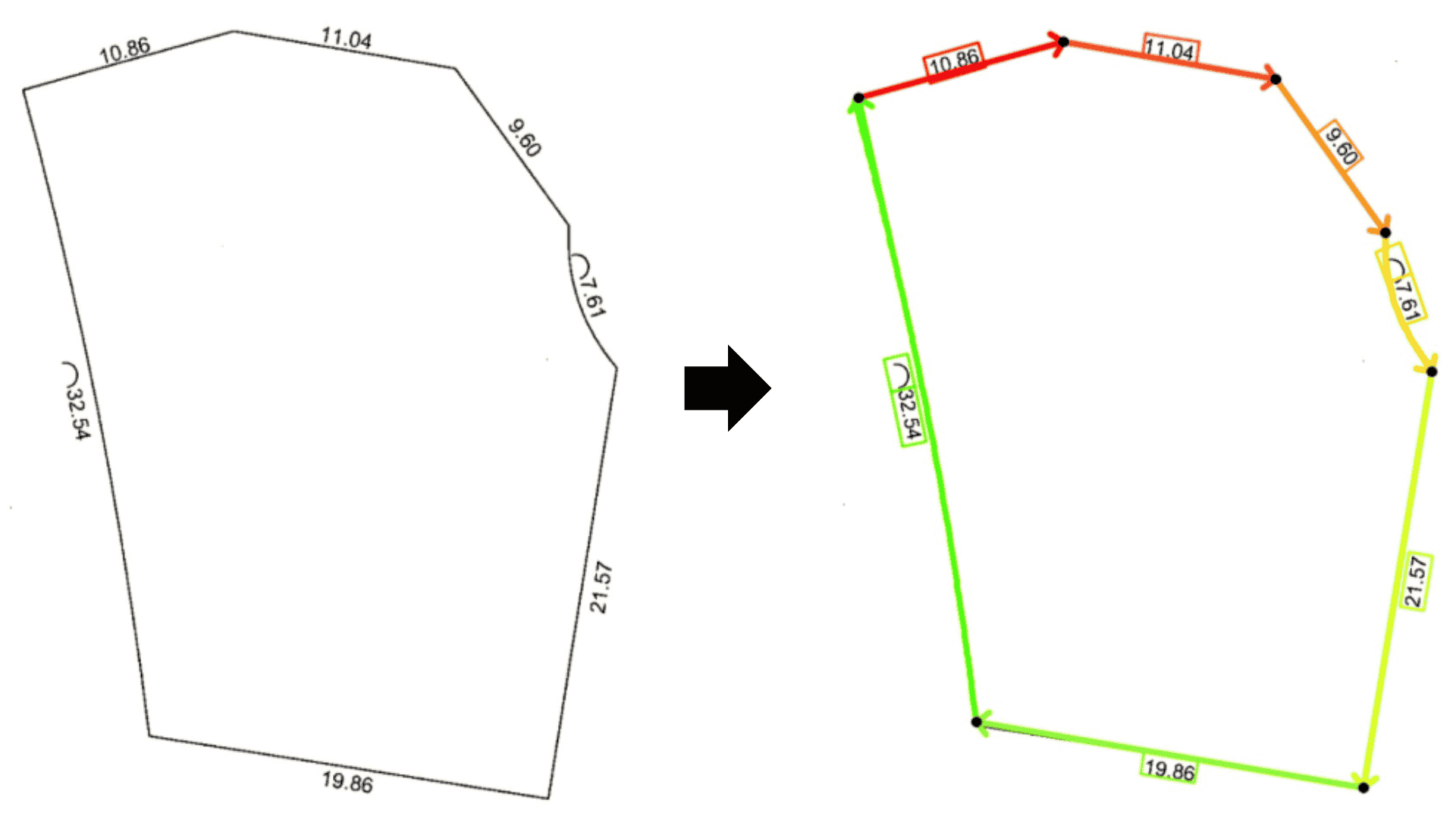
This previous code would display something like the following image:
Advanced Manipulation
Relative Positioning
If you have a similar use-case where you need to create geometrical objects next to pre-existing geometrical objects on the image, you can get inspired by this section.
In the previous example, we displayed not only the OCR boxes but also boxes when
on the symbol "angle" on the left of some OCR boxes. Here is the section of code you would need to add:
| ocrmo_angle_flags: list[bool] = ...
for is_angled, ocrso, color in zip(
ocrmo_angle_flags, ocrmo.ocrsos, colors
):
if is_angled:
shift = -ocrso.bbox.get_vector_left_from_topleft(0).normalized * 40
segment_left = Segment(
[
ocrso.bbox[0],
ocrso.bbox.get_vertice_from_topleft(0, "bottomleft"),
]
)
segment_right = segment_left.copy().shift(shift)
square = Rectangle(
[
segment_right[0],
segment_left[0],
segment_left[1],
segment_right[1],
],
regularity_rtol=0.1,
)
im.draw_polygons(
polygons=[square],
render=PolygonsRender(thickness=2, default_color=color),
)
|
Cardinal Direction
Otary provides a set of tools to help you work with cardinal directions.
Cardinal directions are East (E), North (N), West (W) and South (S).
Otary allows you to get even more fine-grained directions from your directec linear
objects.
Level-2 cardinal directions such as NE, NW, SE, SW.
Level-3 cardinal directions such as NNE, NNE, SSE, SSW etc...
From a Segment or a Spline, you can get the cardinal direction of the
object.
Given the previous image, you could extract the cardinal direction of each
directed linear object like so:
| import otary as ot
from otary.geometry.discrete.linear.directed.entity import DirectedLinearEntity
dle: list[DirectedLinearEntity] = ...
results: list[str] = []
for entity in dle:
cardinal_direction = entity.cardinal_direction(
full=False, # whether to return just E not East for example
level=2 # level of angle detail (1 = N/E/S/W, 2 = N/NE/E/SE, 3 = N/NNE/NE/ENE)
)
results.append(cardinal_direction)
print(results) # ["E", "E", "SE", "S", "S", "O", "N"]
|